Control principle of power regulator
Release time:2023.07.23 Source:MSWER Views:154
A power regulator is a disk mounted power adjustment unit that uses thyristors (also known as thyristors) and their triggering control circuits to adjust load power. Nowadays, more emphasis is placed on using digital circuits to trigger thyristors for voltage and power regulation.
The three-phase thyristor closed-loop technology thyristor voltage regulator adopts phase-shift trigger control method, and the output voltage, current or power can be continuously adjusted, with the characteristics of constant voltage, constant current or constant power. The principle diagram of the trigger board for three-phase thyristor closed-loop technology is based on a typical dual closed-loop control, with the current loop as the inner loop and the voltage loop as the outer loop. Now let's introduce the control principle of the voltage regulator with its "constant voltage control characteristic". The adjustment process is as follows: given signal (Ug), voltage feedback signal (Uf), current feedback signal (If)
When the output voltage of the voltage regulator decreases for some reason (such as a decrease in grid voltage): (Ug-Uf) ↑ → UO ↑ → Uy ↑ → α ↓ → The output voltage of the voltage regulator U ↑ * reaches a balance between Uf and Ug, and the voltage regulator outputs a stable voltage.
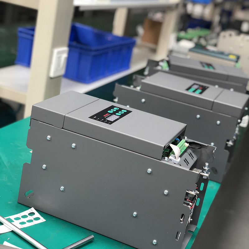
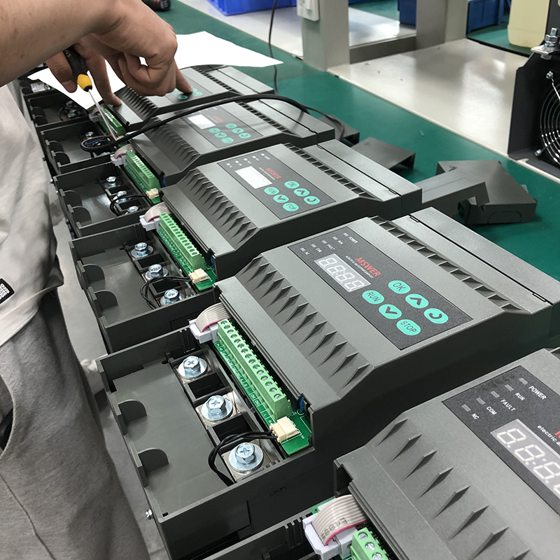
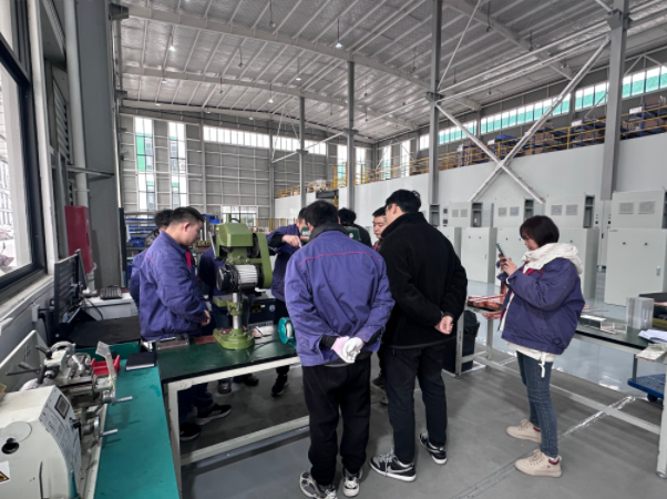
MSWER Electric has been specializing in the research and development of power regulators, various high-power AC/DC power systems, water treatment power supplies, and other special power systems for 17 years. We offer one-stop design and production, and are the source manufacturer! Welcome to consult MSWER, we will provide you with detailed answers to related questions!
The three-phase thyristor closed-loop technology thyristor voltage regulator adopts phase-shift trigger control method, and the output voltage, current or power can be continuously adjusted, with the characteristics of constant voltage, constant current or constant power. The principle diagram of the trigger board for three-phase thyristor closed-loop technology is based on a typical dual closed-loop control, with the current loop as the inner loop and the voltage loop as the outer loop. Now let's introduce the control principle of the voltage regulator with its "constant voltage control characteristic". The adjustment process is as follows: given signal (Ug), voltage feedback signal (Uf), current feedback signal (If)
When the output voltage of the voltage regulator decreases for some reason (such as a decrease in grid voltage): (Ug-Uf) ↑ → UO ↑ → Uy ↑ → α ↓ → The output voltage of the voltage regulator U ↑ * reaches a balance between Uf and Ug, and the voltage regulator outputs a stable voltage.
MSWER Electric has been specializing in the research and development of power regulators, various high-power AC/DC power systems, water treatment power supplies, and other special power systems for 17 years. We offer one-stop design and production, and are the source manufacturer! Welcome to consult MSWER, we will provide you with detailed answers to related questions!
News recommendation
What are the advantages of power regulators?
2024-11-23

The company donated money to the disaster area about the extremely heavy rainstorm event in Henan
2021-07-26
What is the working principle of a thyristor regulator for power regulation
2023-05-24

What is the difference between power regulators and solid-state relays?
2022-10-19
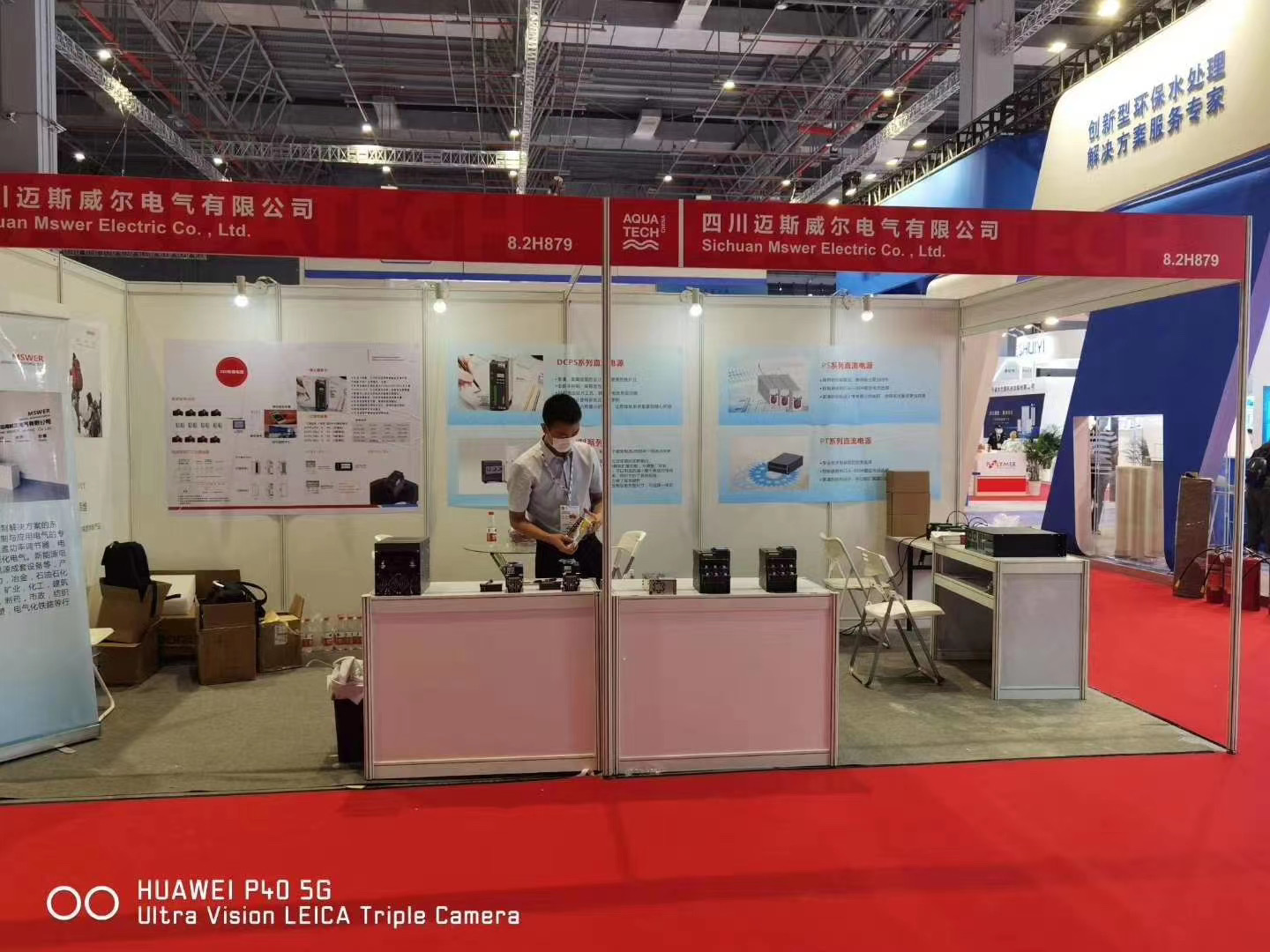
Company's participation in the exhibition in Shanghai
2021-06-11


 Online
 Tel
Tel